Line Reactor
What is a Line Reactor?

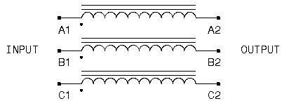
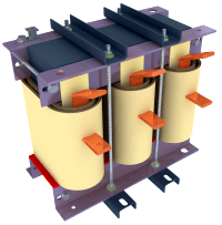
What is a reactor? Essentially a reactor is an inductor. Physically it is a coil of wire that allows a magnetic field to form around the coil when current flows through it. When energized, it is an electric magnet with the strength of the field being proportional to the amperage flowing and the number of turns. A simple loop of wire is an air core inductor. More loops give a higher inductance rating. Quite often some ferrous material such as iron is added as a core to the winding. This has the effect of concentrating the lines of magnetic flux there by making a more effective inductor. An inductor has the characteristic of storing energy in the magnetic field and is reluctant to a change in current. The main property of a reactor is it inductance and is measured in henrys, millihenrys or microhenrys. In a DC circuit (such as that of the DC bus in an AC drive), an inductor simply limits the rate of change of current in the circuit since current in an inductor wants to continue to flow at the given rate for any instant of time. That is an instantaneous increase or decrease in applied voltage will result in a slow increase or decrease in current.
What are good reasons to use reactors?

- Using an AC Line Reactor as a line voltage buffer:
Line switch gear, contactors and disconnectors can cause line transients when inductive loads such as motors are switched off. In such cases, a voltage spike may occur at the input to the drive that could result in a surge of current at the input. If the voltage is high enough, a failure of the semiconductors in the DC converter may also result. Sometimes a reactor is used to "buffer from the line". While a DC link choke will protect against a current surge, it cannot protect the converter from a voltage spike since a link choke is located after the converter. The semiconductors are exposed to whatever line voltage condition exists. For this reason a reactor at the input to the drive may be of some help. A reactor does not fix grounding issues nor does it provide isolation. While a reactor provides some buffering, it does not provide isolation and cannot take the place of an isolation transformer. - Use an AC Line Reactor at the Input to reduce Harmonics:
Most standard "six pulse" drives are nonlinear loads. They tend to draw current only at the plus and minus peaks of the line. The current wave-form is not sinusoidal the current contain "harmonics". For a standard 3 phase input converter to convert AC to DC using six SCR's or six diodes and a filter capacitor bank. The three phase input current may contain harmonic distortion. If a line reactor is installed the peaks of the line current are reduced and somewhat broadened out. This makes the current somewhat more sinusoidal, lowering the harmonic level. This effect is also beneficial to the DC Filter capacitors. - AC Line Reactors at the drive output to increase load inductance:
Applying a reactor at the output of a drive is necessary. If the motor has a "low leakage inductance" a reactor can help bring the total load inductance back up to a level that the drive can handle. In some rare cases where a strange motor configuration or a motor with 6 or more poles is used, the motor inductance may be too low and a reactor may be needed. Running multiple motors on one drive may also result in a low inductance load and the requirement of an output reactor. - Reactors at the drive output to reduce the effect of reflected wave:
A reactor at the output of a drive is sometimes installed in order to prevent a reflected wave voltage spike when long motor leads are required. Though the reactor will slope off the voltage rise time providing some benefit, it is not likely to limit the peak voltage at the motor. In some cases, a resonance can be set up between the cable capacitance and reactor that causes even higher voltages to be seen at the motor. If a reactor is installed at the output, it is most likely part of a specially designed "reflected wave reduction" device that also has damping resistors in parallel. If a reactor is used at the output, it should be located as close to the drive end as is possible. - Sizing an AC Line Reactor:
The first rule is make sure you have a high enough AMP rating. Impedance value, you will usually find that 3% to 5% is the norm with most falling closer to 3%. A 3% reactor is enough to provide line buffering and a 5% reactor would be a better choice for harmonic mitigation if no link choke is present. Output reactors, when used, are generally around 3%. This percent rating is relative to the load or drive where the reactor impedance is a percent of the drive impedance at full load. Thus a 3% reactor will drop 3% of the applied voltage at full rated current.
A reactor is not a magic but can prevent certain problems. Reactors can be helpful in providing some line buffering or adding impedance especially for drives with no DC link choke. For small drives they may be needed to prevent inrush or provide reduction in current harmonics when many small drives are located at one installation. At the output they should only be used to correct low motor inductance and not as a motor protection device.
- Use a reactor:
- To add line impedance.
- To provide some light buffering against low magnitude line spikes.
- To reducing harmonics.
- To compensating for a low inductance motor.
- Only as part of a filter for reflected wave reduction
- Go back to the previous page.
- Use the search bar at the top of the page to search for your products.
- Follow these links to get you back on track!
Store Home | My Account

 United States